Tuesday, September 26, 2017

Reading Consumption Data from a Smart Electric Meter

Back in 2011 I enrolled in the NSTAR Smart Energy Pilota Smart Grid Program offered by my electricity provider. I was given a set of Tendril Home Area Network Equipment that included an Insight wireless display and a web portal on which I could monitor my electricity consumption on a minute by minute basis. I found this quite useful in getting me to change my behavior on how and when I used power. Unfortunately NSTAR decided to end the program in 2014 and disabled the hardware.

https://www.greentechmedia.com/articles/read/massachusetts-mulls-smart-meter-pilots-5987#gs.3vSg7JE

In 2017 I decided to install rooftop solar panels and a NET meter. While the PV array can be monitored via a web portal to get hourly production data, Eversource (formerly NSTAR), only provides consumption readings once a month as part of their billing process.

Would it be possible for me to get data directly from my NET meter in the same way that the Tendril equipment did? 
YES!
I found this old article on HackADay:
which then linked to an active project using low cost hardware and open source software:
Unfortunately most of the hardware recommended in 2014 was no longer available; however, in reading through the extensive comments on bemasher's website led me to believe that as long as I had an rtl-sdr USB dongle that used the RTL2832U and R820T chipset, it would work.

[ a clarification from bemasher: Any rtl-sdr compatible radio will work, not just the R820T tuner. See http://osmocom.org/projects/sdr/wiki/rtl-sdr#Supported-Hardware 

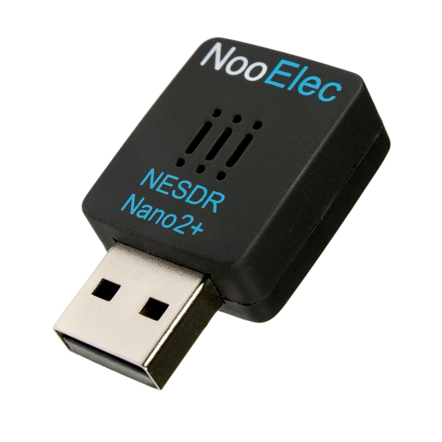
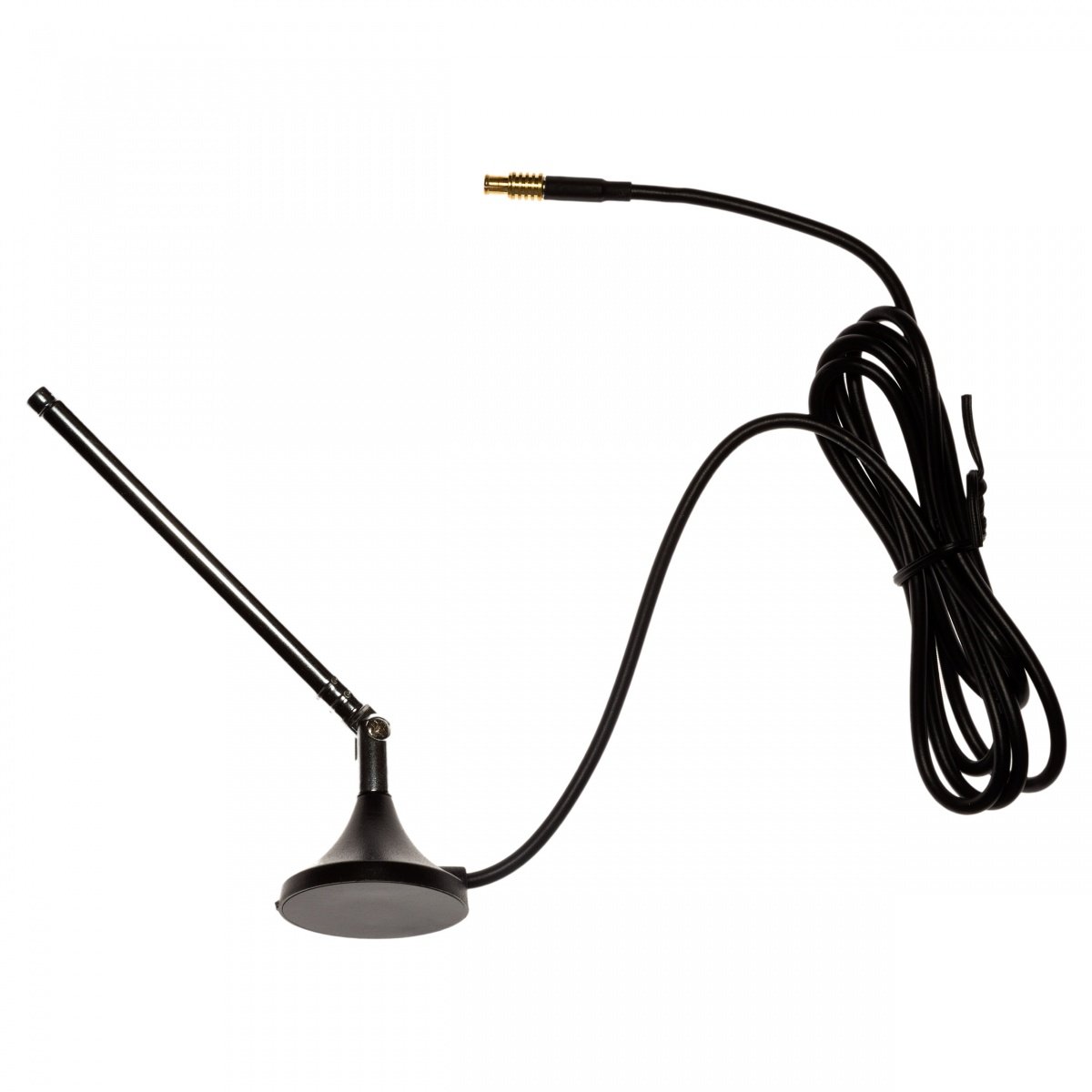
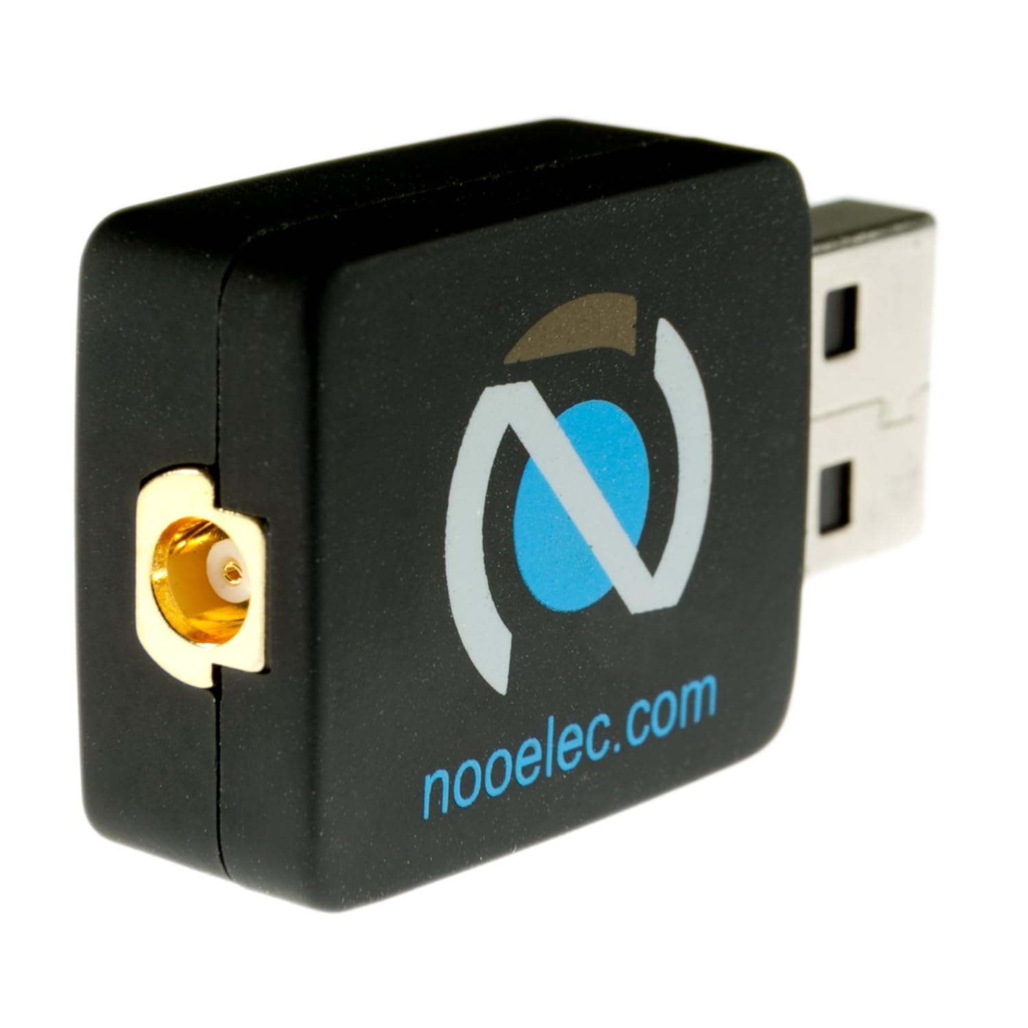
I ordered a $24 NooElec NESDR Nano 2+ from Amazon; my decision was based primarily on the smaller form factor, lower phase noise, 2 year warranty, and that it was spec'd for 24/7 operation:


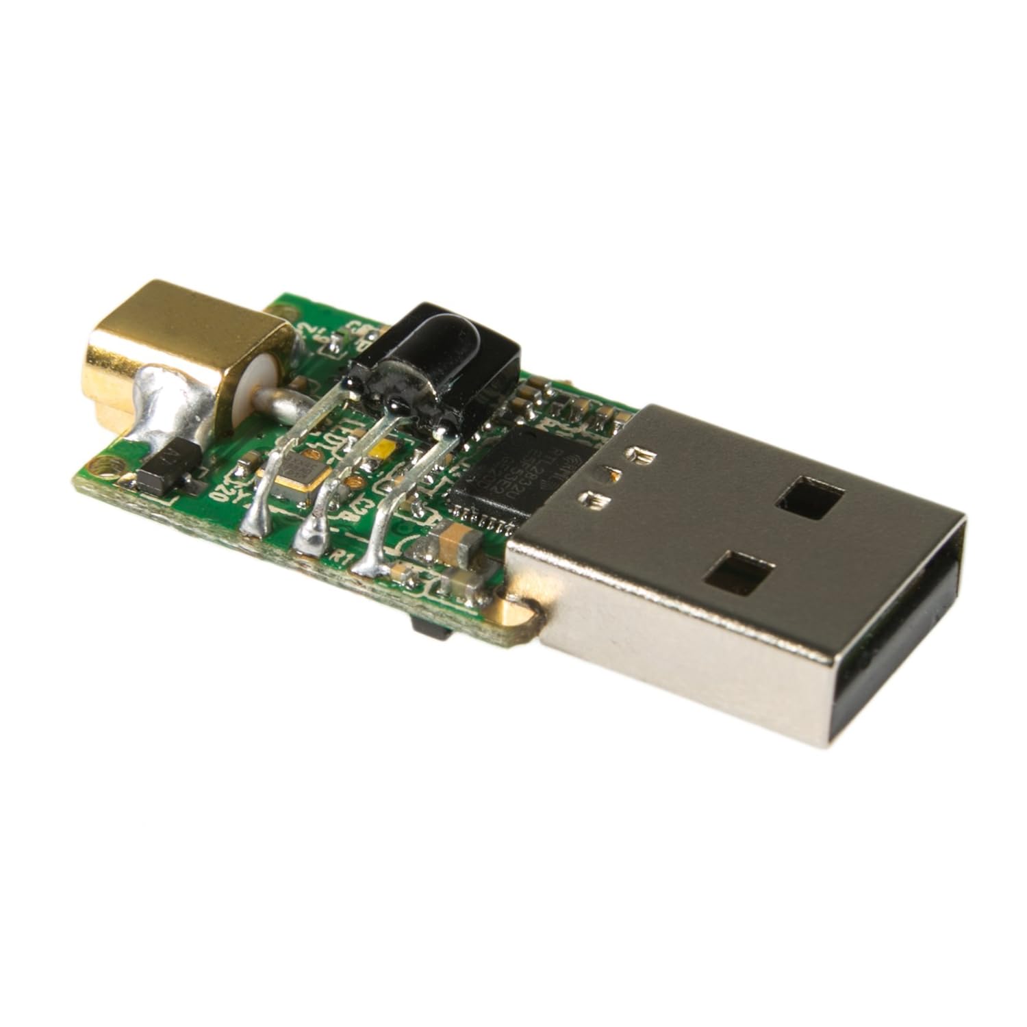
The hardware in the dongle was originally designed by RealTek for use as a digital TV tuner that could be connected to a computer, turning it into a Media Center PC. Hackers quickly discovered that the drivers could be modified to turn the device into a Software Defined Radio (SDR):  
As an SDR, the device can be programmed to scan across a range of frequencies. Once a signal is acquired, it can be demodulated and decoded as shown below:
http://bemasher.net/rtlamr/signal.html
Once the hardware arrived, I decided it would be easiest to use my Windows laptop to do a Proof of Concept before continuing onto my goal of running the code under Linux on a dedicated Raspberry Pi. The following steps were taken:

  • Download and install the SDR drivers for Windows from NooElec. When installing the driver, in the drop down box choose Bulk-In, Interface (Interface 0). This may also sometimes show up as something prefixed with “RTL28328U”. That choice is also valid.

  • Download and install the pre-compiled Windows binaries for rtl_tcp (an I/Q spectrum server for RTL2832 based DVB-T receivers)

  • Install git source control
https://git-scm.com/downloads
  • Install the go build environment


  • Download and build bemasher's rtlamr (an RTL-SDR based Automatic Meter Reader (AMR) decoder:
https://github.com/bemasher/rtlamr

go get github.com/bemasher/rtlamr


  • From a Windows Command Prompt terminal, start rtl_tcp 
  • From a separate Windows Command Prompt terminal, start rtlamr
When I first started rtlamr, I got a deluge of screen prints as I picked up every smart meter in the neighborhood. Fortunately, the tool supports various options to filter the data collection.

First I needed to limit my sample time:
-duration=0s: time to run for, 0 for infinite, ex. 1h5m10s
and then screen out repetitive messages (some meters were sending the same data every 5 seconds):

-unique=false: suppress duplicate messages from each meter
Next, I wanted to look for just my meter:
-filterid=: display only messages matching an id in a comma-separated list of ids.
However, I found that while I could detect and filter my neighbor's Itron C1SR meter using its eight digit Endpoint ID, I could not see my own Itron C4SR NET meter that has a 10 digit ID. It turns out that his older meter was using scm messaging, while mine uses scm+:

  -msgtype=scm: message type to receive: scm, scm+, idm, r900 and r900bcd
With the proper filters in place, I can now see that my meter is reading 99943.64 kWh:
 [click image to enlarge; id's are masked in the screenshots]


Next steps:
  • Move the hardware and software to the Raspberry Pi
  • Set up a database to collect consumption data on an hourly basis
  • Merge in the Solar Array generation data
  • Present combined generation and consumption data on a single web portal

Thursday, July 21, 2016

OSEPP Uno R3 Plus (and minus)

A great place to shop near me in Needham, MA is You-Do-It Electronics, especially when they have one of their seasonal sales.


During last February's "Presidents' Day Weekend" promotion, I found this "'OSEPP™ 101 Arduino Basics Starter Kit' in the bargain bin for $5.00 (normal retail price is around $70):


The contents look pretty good (especially for $5):


But the "OSEPP Uno R3 Plus" board is slightly different than an "ARDUINO UNO":

In particular:
  • Replaced USB-B connector with mini-USB connector
  • Molex connector to connect to OSEPP sensors and other I2C devices.
  • Surface-mount AVR microcontroller instead of a socketed DIP
  • Reset button location changed
  • USB ICSP header pins removed
So I put the kit on the shelf until my son felt like going through the tutorials that do a good job teaching Arduino basics.

Recently I needed a spare UNO to debug some stepper motors for the Shapeoko CNC machine we are building at MIT's Edgerton Center. I raided Zack's desk and setup the Uno R3 Plus, but ran into a problem where XLoader would not upload the pre-compiled hex code that I wanted to test. I then tried using the Arduino IDE to upload the basic "Blink" program and that did not work either.

Going to the OSEPP kits product site to see if 'Blink' was different for the R3 Plus, I saw this statement under 'Tutorial 1':

b) Load the blinking LED example sketch by clicking “File → Examples → Basics → Blink”, and another Windows with the Blink sketch will appear.
c) Select your board by clicking “Tools → Board → Arduino UNO”.  (IMPORTANT: If your sketch does not load properly using this selection, please select Arduino Duemilanove or Nano w/ ATmega328. It was brought to our attention that some of our UNO R3 boards may have been loaded with this bootloader instead (we are embarrassed). Functionally, it is the same so no real concerns. Please accept our apologies!! If you have any concerns, please email Support@osepp.com and you will be looked after!)
I also read here:
DISCONTINUED PRODUCT the UNO R3 is legacy hardware. Production for the UNO R3 has ceased as of June 2016. This page serves as reference material. 
The most recent UNO is the UNO R4: 
http://osepp.com/products/arduino-compatible-boards/uno-r4-plus/

New features in R4: 
• ATMEGA 16U2 Chipset
• Micro USB connector
• 4 additional 5v and GND power pins
• Additional analog pins A6 & A7

“Plus” Features: 
• Replaced mini-USB connector with the more popular micro-USB connector
• removed the Molex connector
Back in the Arduino IDE, I switched the board type from 'UNO' to  'Duemilanova' and got 'Blink' to upload and run. But this same selection change did not work for XLoader. Since I couldn't swap in another AVR chip with the correct bootloader, I decided to see if I could reprogram the AVR chip in place rather than send the obsolete board back to OSEPP for out-of-warranty service.

Instructables has a nice example using the USBtinyISP programmer I had already built to repair our Printrbot controller (see my earlier blog post), but I needed to set up the board on my new laptop. This was somewhat problematic in that my Windows 10 installation did not initially recognize the Windows 7 drivers that I downloaded from Adafruit. Searching the Adafruit forum for the error message "device will not start code 10" produced multiple hits that all involved uninstalling and reinstalling the drivers, which I did without sucess.

Finally I tried one suggestion to use a different USB port, and it worked! (and also now the original port worked, too !?!)

With the USBtinyISP recognized, I connected it to the 6-pin ISP header on the R3 Plus and reflashed the bootloader. Note that avrdude.exe,  avrdude.conf, and the bootloader hex file are all included in the Arduino IDE installation in different subdirectories:
  • Arduino/hardware/tools/avr/bin/avrdude.exe
  • Arduino/hardware/tools/avr/etc/avrdude.conf
  • Arduino/hardware/arduino/avr/bootloaders/optiboot/optiboot_atmega328.hex
For convenience, I copied those files to a single temporary directory so I could run the following command without specifying long path names:
avrdude.exe -C avrdude.conf -b19200 -c usbtiny -p m328p -v -e -U flash:w:optiboot_atmega328.hex -U lock:w:0x0F:m -F
Once that ran successfully, I was able to use the "Arduino Uno" board option in both the IDE and XLoader to upload code to the R3 Plus.

Sunday, July 27, 2014

Conclusion (TLDR)- Fixing a failed 3D printer controller board

Summary

To summarize what was covered in Parts 1, 2 and 3 of "Fixing a failed 3D printer controller board":

Part 3- Fixing a failed 3D printer controller board

Fixing the Printrboard (finally!)

Now that I have an AVR programmer and the software to run it, it's time to hook it up to the failed Printrboard and see if I can fix it. However, there are a few things I wanted be cautious about:

Printer Settings:

Since the printer is hosed, I am not able to get its calibration setting as recommended in Step 4 of the Printrbot reflash guide. When the new firmware is installed, I will need to update the default steps per millimeter and also the printer build volume.
[Note: I actually bumped my volume settings up from 150.0 mm to 152.4mm).

Programming

Unlike prior versions of the Printrboard, the Rev D requires that its Boot jumper be installed when programming the firmware.

Power

A comment on Amazon's product page for the USBtinyISP specifically warns about the functionality of the JP3 jumper that is used to enable/disable +5 volts to the target (similar problems are mentioned for the SparkFun Pocket AVR Programmer where a 3.3v target board was destroyed, possibly caused by +5v leaking through the level shifter chip's output enable pins).

Adafruit's recommended use cases for removing the jumper are:
  • The target is running at +5v, but needs more than the 100 mA of current that the USBtinyISP can supply and so the target needs to run off its own power supply.
  • The target is not running at +5v (e.g., it has a 3.3v chip), so we will use the target's power supply to run the level shifters on the USBtinyISP.
Looking at the Printrboard schematics, I can see that the MCU is a 5 volt part, and also I found an article where someone was able to program their board with only the AVR programmer's power supply connected, so I will:
  • Disconnect the +12V power cable at the Printrboard, but leave all other cables connected.
  • Leave the JP3 jumper installed on the USBtinyISP .

Red Wire?

On the USBtinyISP, Pin 1 of the 6-pin ISP header is clearly marked and the cable that plugs onto it has its red wire at that position:
On the schematic, Pin 1 is the "MISO" signal and Pin 6 is "GND"

The Rev D Printrboard has a 6-pin SPI header labled "ICSP" (In Circuit Serial Programming), but there are no markings to indicate which is Pin 1. Looking at the schematics, the ISP header has Pin 1 connected to "GND" and Pin 6 connected to "MISO" (i.e., numbering is reversed compared to the AVR programmer!):
On the Printrboard artwork, the '1' marking on the ICSP JP4 connector *is* a ground pin;
therefore the "MISO" signal that runs on the red wire should go to the pin closest to the SD card; this would be consistent with how the RepRap wiki says the cable should be connected: 

"Connect the 6 pin programming cable to the Printrboard's ICSP header. 
Pin 1 (red wire) is closest to the SDcard slot."
[Note that the Printrboard artwork markings do not agree with how header pins are usually labeled with even-numbered pins in one row and odd-numbered pins in the other. Also, on the USBtinyISP, the location of the physical pins on the header does not match up with the graphical location on the schematic symbol. So "When in doubt, ohm it out".]

Which Bootloader to Install?

Lincomatic's blog has three different pre-compiled boot loaders to choose from:
  • DFU : Atmel's officially supported bootloader
  • CDC: Integrated with the Arduino IDE
  • HID:  no drivers needed; plug and play
For this repair, I will use the CDC version since that integrates with my existing Arduino development environment.
[Note: once I have the CDC bootloader installed, I will not use Flip to install the printer firmware, but instead will use 'avrdude' via the 'avr109' protocol.]

What AVR Settings to Use?

The AVR chip operation is controlled by a set of internal fuses and lock bits described here (note that the fuses and lock bits use "negative" logic: un-programmed state is '1', programmed state is '0'). The settings are different for the factory DFU bootloader vs CDC bootloader:

          low / high / extended / lock
DFU:  "5e"  / "99"   / "f3" / "3f"
CDC:  "de" / "9b"   / "f0" / "3f"

From a AVR fuse calculator, I see that the differences are
  • Clock divider:      DFU: divide by 8  / CDC: don't divide
  • Boot flash size:     DFU: 4096          / CDC: 2048
  • Brown out level:   DFU: 2.6 V         / CDC: 4.3 V
The difference that interests me is the "brown out level" since I think my firmware corruption could be caused by pulling the printer's power cord. Atmel's AVR documentation specifically mentions this as a method to protect the chip:

29.7.11 Preventing flash corruption
During periods of low VCC, the Flash program can be corrupted because the supply voltage is
too low for the CPU and the Flash to operate properly. These issues are the same as for board
level systems using the Flash, and the same design solutions should be applied.

A Flash program corruption can be caused by two situations when the voltage is too low. First, a regular write sequence to the Flash requires a minimum voltage to operate correctly. Secondly the CPU itself can execute instructions incorrectly, if the supply voltage for executing instructions is too low.

Flash corruption can easily be avoided by following these design recommendations (one is
sufficient):
  1. If there is no need for a Boot Loader update in the system, program the Boot Loader bits to prevent any Boot Loader software updates.
  2. Keep the AVR RESET active (low) during periods of insufficient power supply voltage. This can be done by enabling the internal Brown-out Detector (BOD) if the operating voltage matches the detection level. If not, an external low VCC reset protection circuit can be used. If a reset occurs while a write operation is in progress, the write operation will be completed provided that the power supply voltage is sufficient.
  3. Keep the AVR core in Power-down sleep mode during periods of low VCC. This will prevent the CPU from attempting to decode and execute instructions, effectively protecting the SPMCSR Register and thus the Flash from unintentional writes.
Since I am using the CDC bootloader and using the recommended fuse settings, I hope I will no longer see problems due to cycling power.

As for the lock bits, a completely unlocked chip will have a setting of "3f" (only the lower 6 bits in the lock byte are used; the top two bits are always '0').  They can only be set to an unlocked state by erasing the chip. Erasure is done automatically when programming the chip from 'avrdude'.

Here We Go...

On the laptop where I have configured the USBtinyISP and avrdude:
  • Download the printer firmware I will be installing. I got it from the Printrbot Simple Metal support page (file name "Printrboard_Auto-Level_Firmware_v2.hex", which I then renamed to "firmware.hex" for easier typing later on).
  • Download the CDC bootloader zip file from Lincomatic's blog and extract "BootloaderCDC.hex".
  • Disconnect the power cable from the Printrboard.
  • Install the BOOT jumper onto the Printrboard (Rev D).
  • Install the JP3 voltage jumper on the USBtinyISP.
  • Connect the ribbon cable from the USBtinyISP to the 6-pin ICSP header on the Printrboard (red wire closest to the SD card slot).
  • Connect the USBtinyISP to laptop with a USB A-B cable.
  • Confirm that the USBtinyISP is connected (green LED on programmer).
  • Confirm that the Printrboard is getting power from the USBtinyISP (green LED on target).
  • Reset the Printrboard (press button on board).
  • Open a command prompt on the laptop.
  • 'cd' to the directory where I put the bootloader hex file.
  • Run 'avrdude' to confirm that it can read the Printrboard (red LED flashes on programmer.
> avrdude -c usbtiny -p at90usb1286
  • Check the state of the chip's fuses and lock bits:
> avrdude -c usbtiny -p at90usb1286 -U lfuse:r:-:h -U hfuse:r:-:h -U efuse:r:-:h -U lock:r:-:h
[Note: Fuses read as '0x5e' / '0x99' / '0xf3' ; lock bits are '0x24';
so the fuses are set to the factory DFU default, but the lock bits are not '0x3f'.
Instead a setting of' '0x24' means the the lock byte is configured as '00 10 01 00';
section 30.1 of the AVR chip spec shows that the bootloader is:
    • Not allowed to write to the Boot Loader section.
    • Not allowed to read from the Application section.
    • Further programming and verification of flash and EEPROM is disabled.
  • Re-program the chip's fuses for the CDC bootloader:
avrdude -c usbtiny -p at90usb1286 -U lfuse:w:0xDE:m -U hfuse:w:0x9B:m -U efuse:w:0xF0:m
  • Program the AVR with the new bootloader; this also erases the lock bits:
> avrdude -c usbtiny -p at90usb1286 -U flash:w:BootloaderCDC.hex:i
[Note: if avrdude complains of a verification error, ignore it: the USBtinyISP can write to a 128 KB chip, but can only read back 64 KB, which is why there is a mismatch at byte 0x1f000.]
  • Reset the Printrboard (press button on board)
  • Exit the command window
  • Disconnect the USB cable from the laptop
  • Disconnect the AVR ribbon cable from the Printrboard
  • Make sure the boot jumper is still in place.
  • Connect the power cable to the Printrboard.
  • Connect the external power supply to the printer.
  • Reset the Printrboard so that the board boots into the CDC bootloader
  • Connect the laptop to the printer via USB.
  • The printer should now install onto a new port using the same Teensy USB Serial Driver that I already print with (my printer uses "COM5" for printing, but the new bootloader port is "COM6".
  • Open the command prompt window again and 'cd' to the directory that has the "firmware.hex" file. Use 'avrdude' to upload the firmware via the 'avr109' protocol over the 'COM6' port:
> avrdude -c avr109 -P COM6 -p at90usb1286 -U flash:w:firmware.hex:i 
  • Exit the command window.
  • Reset the Printrboard (press button on board).
  • Remove the BOOT jumper from the Printrboard.
  • Reset the Printrboard again so it starts up as a printer.
  • Open Repetier, and see if it can connect to the printer.
  • Use the manual control tab's g-code entry console to re-enter the original printer calibration settings (M92 steps and M211 build volume) and store them to EEPROM using the M500 command.
  • Re-calibrate the Z offset (M212) and store it to EEPROM with M500.
  • Print a test cube. 
  • Be happy!

    Thursday, July 24, 2014

    Part 2- Fixing a failed 3D printer controller board

    Building the AVR Programmer

    In my previous post, I explained the printer problem I am having and how I planned to fix it using an AVR programmer. Most of the methods I found on-line for re-programming a Rev D Printrboard make use of a "USBtinyISP AVR Programmer" from Adafruit (image below is from their website):
    This device comes in kit form, and as an open-source design, the schematics, drivers, and applications are readily available. I have built several other Arduino shield kits from Adafruit which worked well, so felt confident this would be a good choice (I do have one concern based on a comment on Amazon regarding interfacing to 3.3 volt devices, but I'll discuss that later). 
    The direct order cost with 3-day shipping from NYC to Boston came to less than $32.

    Assembly

    Like most Adafruit kits, this came in a padded envelope as a bunch of parts in an anti-static bag:
    There are no printed instructions provided, but instead the bag has a label that gives the URL to an excellent tutorial on the web. As I have done in the past, I downloaded the guide in PDF format so I could view it on a tablet and easily zoom in to look at images of the parts while I am working.
    The Version 2 of this AVR programmer has several nice features:
    • Low cost: you could breadboard one up for less than $16.
    • All through-hole design (rather than surface-mount) makes for easy assembly.
    • Case with indicator LEDs.
    • Supports both 6-pin and 10-pin bus connectors.
    • Pre-programmed/socketed microcontroller which simplifies repair.
    • Ability to program a target which is running at voltage other than the standard USB +5 volts (maybe...).
    It took me about an hour to assemble the USBtinyISP; I also installed the 'JP3' jumper so that it can supply +5 to the target device being programmed. To test it, I had to load some software onto my laptop. 

    Windows Drivers

    Windows drivers for the USBtinyISP are available from Adafruit; I downloaded the zip file for Win7-64 and unpacked it into a local folder on my laptop. I then connected the assembled USBtinyISP to the laptop with a USB A-to-B cable. The green LED on the programmer came on and I got the pop-up for installing a new driver:
    Instead of letting Windows Update search for new drivers, I selected the option to install from the folder I put the downloaded driver into. Although the Win7-64 driver was unsigned, it installed just fine:
    So what's next?

    AVR, Dude!

    Well, actually "WinAVR" (pronounced "whenever"), which includes the interface program "avrdude" (AVR Downloader Uploader: a program for downloading and uploading the on-chip memories of Atmel’s AVR microcontrollers).
    I installed the latest version of WinAVR onto my laptop (avrdude 5.5 and newer has support for "usbtiny"; get it here)  and then followed these instructions to test my USBtinyISP.
    • On the Win7 laptop, open a 'cmd.exe' window and type the command 'avrdude' to see if the program installed correctly:

    • Next, type the command again with options to specify the programmer and the target chip:
      • > avrdude -c usbtiny -p at90usb1286
    • Success! It communicated with the programmer! (but did not find a connected chip)
    In the next post, I will hook up the Printrboard and see if it can be fixed.

    Tuesday, July 22, 2014

    Fixing a failed 3D printer controller board

    The Problem

    My son recently got a 3D printer from Printrbot and has been doing some interesting things with it; however, we started to see some odd behavior after adding an LCD display and so decided to update the firmware on the printer controller. Unfortunately, while following the steps for this, we got a screen from the Atmel Flip application, showing the message "Blank check fail at 0x00000":


    We contacted Printrbot support and were told:

    "The Blank Check Fail is, basically, the kiss of death for these boards and the only option is to buy a new Printrboard."

    Before spending $100 for a new board, I decided it was worth some more investigation to see if I could fix the existing board myself.

    What I Found

    Several Google searches led to various postings I found helpful at:
    It seems that the "Blank check fail" message can be caused by corruption of the firmware on the Printrboard, specifically a section that provides read/write protection of the code (i.e., the "lock bits"). If these are enabled, it is not possible for the Flip firmware updater to erase the flash memory (causing blank check to fail) and re-write new code to the board (causing verify to fail). What leads to this corruption is not clear:
    • I have had the code fail to reboot after initiating an "Emergency Stop" from Repetier or after killing power to abort operation during a head crash.
    • Some users reported it happening during a firmware update with the printer's Y-stop switch activated. 
    • Our most recent failure came after trying to use the LCD controller to initiate a print by reading a gcode file off an SD card and pulling the power cord when the display went haywire.
    Unfortunately, clearing the lock bits is not something that can be done from Flip; instead, direct access using an AVR programmer is required.

    Why do we need an AVR Programmer?

    The Printrbot Simple Metal (Model 1403) that my son bought as a kit in April 2014 uses a Rev D Printrboard controller (images are from the Printrbot Store):

    The board is a Teensylu derivative that uses an Atmel AVR MCU chip: AT90USB1286. 
    This device features:
    • 128 Kbytes flash program memory
    • 8 Kbytes SRAM data memory
    • 4 Kbytes EEPROM data memory
    [Note: the AT90USB1287 chip has additional USB "OTG" functionality that allows it to function either as a host or a client.] 

    The chip's flash program memory is divided into two sections:
    • Application Program (the printer firmware, programmed by user)
    • Boot Program (the USB bootloader, programmed at the factory, used to update the firmware)
    The Printrboard has a jumper that determines which program section runs on power up or on board reset; on our Rev D board:
    • Jumper removed: Printer application runs
    • Jumper installed: Boot loader runs
    Each section also has dedicated "lock bits" for write and read/write protection. These bits are *not* accessible from the Application or Boot programs, but *can* be updated via JTAG or through the board's 6-pin ISP (In-Service Programming) header, using the SPI (Serial Peripheral Interface) bus. 

    An AVR programmer that interfaces to this ISP header should allow us to
    • Check and change the state of the lock bits.
    • Update the Boot loader program to a factory-fresh state so we can reload the printer firmware.
    • Optionally install an alternate boot loader that provides different functionality.
    In my next post, I'll write about building and configuring a low-cost programmer that we will use to try and fix the failed Printrboard.